1.3.1
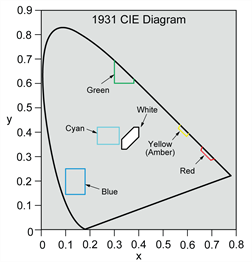
Aviation colors available include Green, Red, Blue, White, Yellow (Amber), and Cyan as described in Figure 1.3.1-A.
|
|
|||||||||||||||||||||||
Sunlight Readability - Aviation (Display Type S)
Type S displays are sunlight readable and meet the contrast ratio requirements of MIL-PRF-22885 with an opaque black background containing indiscernible legends until illuminated. When energized at rated voltage, the display legends are readable in 10,000 footcandles of direct sunlight including any glare producing angle up to 15° and 30° to the normal of the viewing surface. When the display is not energized the legends are hidden and cannot be read in direct sunlight. The display contrast values meet or exceed the minimum contrast requirements of MIL-PRF-22885.
The minimum contrast values for each color at full rated voltage are shown below.
|
Figure 1.3.1-B Minimum Contrast Ratios |
||
|---|---|---|
| Color | Contrast @ 15° | Contrast @ 30° |
| Blue | 0.60 | 0.30 |
| Green | 0.60 | 0.30 |
| White | 0.60 | 0.40 |
| Yellow (Amber) | 0.60 | 0.40 |
| Red | 0.60 | 0.30 |
| Cyan | 0.40 | 0.20 |
See Appendix D for information about the luminance of other cap voltage options.